Fibre dispersion explained refers to the way optical signals spread out as they travel through fibre optic cables, affecting signal clarity and transmission quality. In optical communication systems, this phenomenon plays a critical role in determining how fast and how far data can be transmitted without distortion. This article breaks down what fiber dispersion is, why it happens, and why it is such an important factor in modern high-speed communication networks.
When studying optical communication, we often encounter the term “dispersion”. This word may seem like a negative term. Whenever dispersion is mentioned, it is rarely in a positive context, usually referring to signal distortion or reduced transmission performance.

Today, driven by AI, optical communication is developing rapidly, with speeds increasing from 400G and 800G to 1.6T and 3.2T. In this process, experts often emphasise the need to reduce and manage dispersion in order to maintain signal integrity and performance.
So, what exactly is dispersion? Why does it have such a major impact on optical communication? Can it be controlled or overcome?
What is dispersion?
Dispersion is actually a simple physical phenomenon. As the name suggests, it refers to the separation or spreading of light into different components.

A common example is a prism. In physics, we learn that when sunlight passes through a prism, it splits into a spectrum of colours ranging from red to violet. This is a form of dispersion.
The reason is that sunlight is not a single wavelength (monochromatic light), but a mixture of many wavelengths (polychromatic light). When this mixed light enters a prism, each wavelength is refracted at a slightly different angle due to differences in refractive index, causing the light to spread out.
In addition to prisms, diffraction gratings and interferometers can also produce dispersion effects through interference and diffraction principles.
Dispersion itself is not a negative phenomenon. It is neutral and widely used in science and engineering. For example, spectrometers and spectrophotometers rely on dispersion for chemical analysis, biological monitoring (such as concentration and purity), astronomical spectroscopy, material identification, and gemstone analysis.
What is fibre dispersion?
The dispersion discussed in optical communication refers specifically to fibre dispersion.
Many people think of optical fibre as simply a thin glass strand that carries light. In reality, signal transmission inside optical fibre is far more complex.
The optical signals used in communication are not pure single-wavelength beams. Instead, they are composed of multiple wavelengths and multiple propagation modes.
As these signals travel through the fibre, different components move at slightly different speeds due to variations in wavelength, material properties, and waveguide structure. This causes an optical pulse that starts out sharp and well defined to gradually spread out over distance. Eventually, this leads to signal distortion, overlap, and loss of clarity. This phenomenon is known as fibre dispersion.
Simply put, it is similar to a group of runners starting in perfect formation but gradually spreading out as some run faster and others slower. By the time they reach the finish line, the original order is lost.
Although the speed differences in light are extremely small, the effect becomes significant over long distances and at very high transmission speeds.
For example, if two wavelengths travel at slightly different speeds and are transmitted over 1000 kilometres, even a tiny difference can result in a measurable delay. In high-speed systems transmitting billions of bits per second, this delay is enough to cause signal overlap and data errors.
Hazards of fibre dispersion
The impact of fibre dispersion on communication can be seen in several key areas:
1. Reduced transmission distance
Dispersion causes optical pulses to broaden as the distance increases. Eventually, adjacent pulses begin to overlap, making it difficult for the receiver to distinguish between binary signals (0 and 1). This limits the maximum transmission distance unless compensation techniques are used.
2. Limits transmission speed
Higher transmission rates require narrower optical pulses. However, narrower pulses are more sensitive to dispersion. This means dispersion directly restricts how fast data can be transmitted over fibre.
3. Increases error rate
Bit error rate (BER) measures the proportion of incorrect bits received in a transmission. Dispersion increases inter-symbol interference, which directly raises the BER. When the error rate becomes too high, communication quality degrades, causing delays, interruptions, or data loss.
4. Affects signal stability
Dispersion is influenced by multiple factors and can vary with temperature, wavelength, and fibre conditions. This leads to fluctuations in signal quality over time, reducing overall stability.
Main types of fibre dispersion
Fibre dispersion is mainly divided into three types: modal dispersion, material dispersion, and waveguide dispersion. These effects can occur independently but also combine to influence overall signal behaviour in optical fibres.
Modal dispersion is mainly found in multimode fibres, while material dispersion and waveguide dispersion are present in all types of optical fibre systems.
Modal dispersion

To understand modal dispersion, it is important to distinguish between single-mode and multimode fibre.
Single-mode fibre has a very narrow core (typically around 9 micrometres), allowing only one propagation mode of light to travel through it.
Multimode fibre has a larger core (typically around 50 micrometres), allowing multiple light modes to propagate simultaneously.
Modal dispersion occurs in multimode fibres because different light modes travel along different paths and therefore arrive at the receiver at slightly different times. This spreads out the original pulse and reduces signal clarity.
Modal, Material, and Waveguide Dispersion
The larger the core diameter of an optical fibre, the more propagation modes it supports, and the more severe modal dispersion becomes. Single-mode fibre, which allows only one propagation mode, has almost no modal dispersion. This is why single-mode fibre can transmit over much longer distances than multimode fibre.
In practical applications, multimode fibre is mainly used for short-distance communication, such as local area networks in office buildings and equipment connections in data centres, typically within a few hundred metres.
Material Dispersion
Material dispersion is caused by the inherent optical properties of silicon dioxide (glass), the core material of optical fibres.
We know that light travels at different speeds in different media, and silicon dioxide has a wavelength-dependent refractive index. Longer wavelengths experience a lower refractive index and travel faster, while shorter wavelengths experience a higher refractive index and travel slower.
As previously mentioned, optical signals in fibre communication are not single-wavelength monochromatic light, but rather a spectrum of wavelengths within a certain range.
For example, common laser sources used in fibre communication operate around 1310 nm or 1550 nm, but in reality they contain a small wavelength range such as 1300–1320 nm or 1540–1560 nm.
Because different wavelengths travel at different speeds in silica fibre, they arrive at different times after long-distance transmission. This effect is known as material dispersion.
Material dispersion is strongly wavelength dependent. It is significant in the 850 nm region, but reaches a minimum around 1310 nm.
This is one of the key reasons why early fibre optic systems selected 1310 nm as a transmission window.
Waveguide Dispersion
Waveguide dispersion is caused by the physical structure of the fibre itself, including core diameter, cladding properties, and refractive index distribution. It is related to the waveguiding nature of optical fibres.
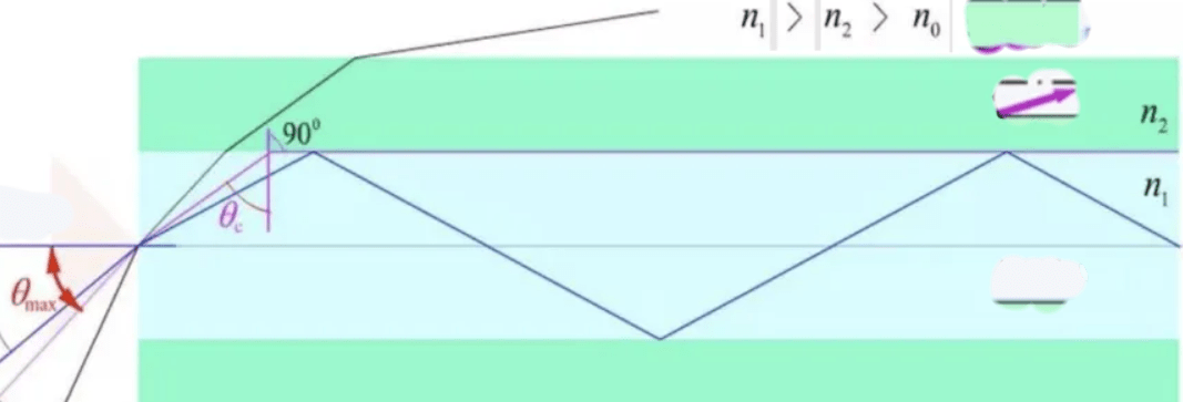
In fibre optics, the refractive index of the core is higher than that of the cladding, allowing light to propagate through total internal reflection at the core–cladding boundary, as described by RP Photonics – Total Internal Reflection.
However, not all optical energy is confined strictly within the core. A portion of the light extends into the cladding as an evanescent field.
Waveguide dispersion occurs because different wavelengths distribute their energy differently between the core and cladding. Shorter wavelengths are more confined to the core, while longer wavelengths extend further into the cladding and are more influenced by its properties.
This difference in energy distribution causes different effective propagation speeds for different wavelengths, leading to pulse broadening. This is waveguide dispersion.
In practice, material dispersion and waveguide dispersion combine to form chromatic dispersion, which is the dominant form of dispersion in single-mode optical fibres.
Dispersion Compensation Techniques
Dispersion is a major limiting factor in optical communication system performance. As a result, many compensation techniques have been developed to reduce or eliminate its effects.

Dispersion Compensating Fibre (DCF) Technology
A dispersion-compensating fibre is a specially designed fibre with dispersion characteristics opposite to standard transmission fibre.
At 1550 nm, standard single-mode fibre exhibits positive dispersion (pulse broadening), while DCF exhibits negative dispersion (pulse compression).
By connecting DCF in series with standard transmission fibre, positive and negative dispersion can cancel each other out. This is a widely used method in long-distance backbone networks.
For example, in a 1000 km transmission system, DCF modules are typically inserted every 100–200 km to compensate for accumulated dispersion.
However, DCF introduces additional optical loss, which increases system attenuation and requires optical amplifiers for compensation.
Optical Time Division Multiplexing (OTDM)
Optical Time Division Multiplexing reduces dispersion impact by shortening pulse width and increasing repetition rate.
In simple terms, it makes optical pulses narrower so that even after broadening, they do not overlap with adjacent pulses.
The goal is to improve time resolution so that the receiver can distinguish closely spaced pulses and avoid inter-symbol interference.
OTDM is mainly used in high-speed short-distance systems, such as data centre interconnects. However, it requires extremely advanced lasers and detectors, making it costly and complex.
Dispersion Slope Compensation
Standard dispersion compensation is usually optimised for a single wavelength. However, in Wavelength Division Multiplexing (WDM) systems, multiple wavelengths are transmitted simultaneously, each experiencing different dispersion levels.
Dispersion slope compensation addresses this by designing compensation structures that correct dispersion variation across multiple wavelengths, ensuring consistent performance across the full spectrum.
Electronic Dispersion Compensation (EDC)
Electronic Dispersion Compensation works differently from optical methods. Instead of correcting dispersion in the optical domain, it uses digital signal processing (DSP) at the receiver to reconstruct the original signal.
The distorted optical signal is converted into an electrical signal, processed, and corrected to remove inter-symbol interference.
EDC is flexible, cost-effective, and widely used in short-distance high-speed systems such as data centres and access networks.
For example, modern home fibre broadband routers often include built-in electronic dispersion compensation modules.
Future Directions of Dispersion Compensation
As optical communication speeds continue to increase, tolerance to dispersion becomes even lower. Future development focuses on two main directions: improved fibre design and advanced compensation techniques.
Optimised Fibre Structures
A key example is photonic crystal fibre, which uses a periodic microstructure to control light propagation and dispersion characteristics. It can achieve near-zero or even negative dispersion and is a major research area in modern photonics.
Adaptive Dispersion Compensation
Adaptive systems monitor dispersion changes in real time and dynamically adjust compensation parameters based on environmental conditions such as temperature or fibre ageing, ensuring stable signal quality.
Optical OFDM Technology
Optical Orthogonal Frequency Division Multiplexing (OFDM) divides the signal into multiple low-rate orthogonal subcarriers. Each subcarrier is less sensitive to dispersion, significantly improving robustness in high-speed transmission systems.
Conclusion
That concludes the introduction to fibre dispersion.
Although dispersion is invisible in everyday life, it plays a critical role in shaping modern communication systems. It acts as an invisible limiting factor that affects signal quality, transmission distance, and data speed.
The ongoing challenge between engineers and dispersion continues to drive innovation in optical communication. With continued advances in fibre design and compensation technologies, future systems are expected to achieve even higher speeds, longer distances, and greater efficiency, pushing optical communication to new levels.
Leave a Reply